
Hi everyone, one of my first serious posts here. I bought a 2006 V70R last May (2017), and have been loving it so far - 4th owner on the car, and it's almost all stock. I'm fairly new to doing work on my car myself, but I've been wanting to learn and I'm enjoying it a lot! Once I found out about VIDA/DICE, I grabbed one immediately and it's been really useful in guiding me through troubleshooting. I recommend one to anyone doing their own car work on a Volvo.
I'm hailing from Cambridge Ontario, so if you're in the area, gimme a shout! I'll be happy to do a VIDA read if you're in need.
Work I've done so far on the car hasn't been too involved:
1. All new rotors/pads installed
2. Brand new headlights installed
3. Rebuilt headlight wiper motors
I digress, this post is really a 'how-to' on cleaning both the MAF sensor, and throttle body.
If you know your way around all this stuff, I'm actually interested in your input on a few things that made me raise an eyebrow, so you could skip to the end and look at that (or read it all, that's cool too), and I'd really appreciate any insights. Thanks in advance!
Diagnosis:
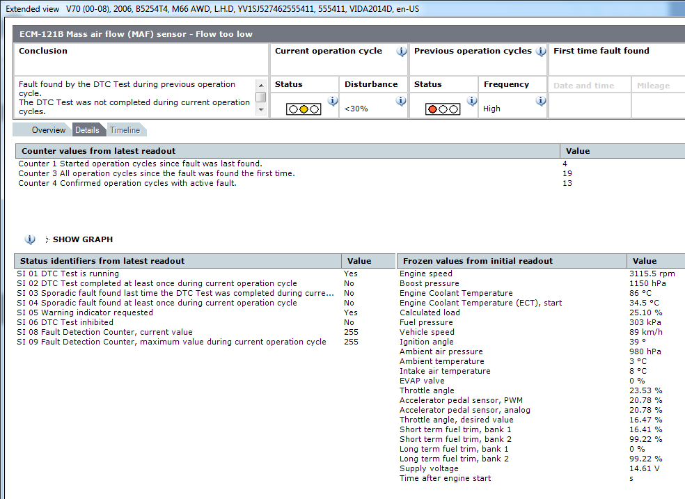
Couple weeks ago, I had a check engine light come up. I pulled it up and the DTC was 'ECM-121B Mass air flow (MAF) sensor - Flow too low'. I cleared it, and watched to see if it would come up again since I hadn't actually noticed any poor performance while driving.
Just in the last week, the DTC came up again and I would get some pretty reduced engine performance at times - with an audible change in engine note. It would feel like the power suddenly dropped out for a short while even though I still kept accelerating, and then would come back shortly after. Mucking around, I was able to start reproducing it fairly reliably as I would accelerate moderately in 4th (I have an M66), to about 70km/h as I go by 2500rpm.
Here's a shot of the details that I pulled up later.
![Image]()
I also noticed that when I would start the car cold, the engine speed would jump right to idle, around 750rpm. Before all this started happening, it would start just below 2000rpm (sometimes flutter around up there), then shortly drop to 1000rpm, and then a short while later down to idle around 750rpm. So that was new behavior.
VIDA being such a nice tool, with so many sensors accessible and able to feed me information live (even in a plot), I wanted to see what was going on. So, I plugged in with a laptop, picked a few sensors to watch that I thought might be relevant, and went for a drive. I won't bore you with 30min of video capture, and me not realizing the mic was recording, and instead show a screen capture.
I caught 4 good instances of the engine performance drop out (red arrows to indicate), and they all coincided with a sudden drop in the MAF value (blue line), even though I was under constant throttle to accelerate at the time - notice the engine RPM continuing up (green line). I don't know why the vehicle speed wasn't updating in the list, but this was happening around 70km/h.
![Image]()
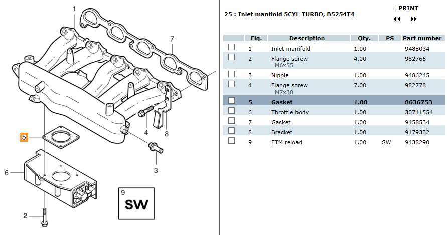
So I started digging around online for some direction on how to clean a MAF, and also found that the throttle body (TB) downstream can also impact the airflow, and looking into that, it should be cleaned too. Now I had some direction. Below are a couple links to the information I used to figure out what I was going to do, in addition to service instructions within VIDA. It's been stressed in forum posts (and in the VIDA instructions) to replace the TB gasket on removal, so I did that.
Removal/cleaning video:
Cleaning Video:
I also checked local prices for new parts, MAF ~$200+tx, TB ~$415+tx (Canadian prices). So cleaning rather than replacing was my first choice.
Tools / Materials:
• Torx driver set - usually used T25
• Socket set - 7mm, 8mm, 10mm
• Slot screw drivers
• Pliers
• Rags
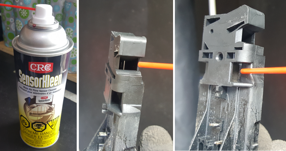
• MAF cleaner - I used 'CRC, SensorKleen'
• Throttle Body cleaner - I used 'CRC, Throttle Body Kleen'
• New throttle body gasket (Volvo PN: 8636753)
![Image]()
Plan/Steps:
I wrote up my plan and steps to follow based on what I read, so I would botch it and forget something. Feel free to follow these steps!
MAF/TB Removal:
i. Capture Error codes
ii. Watch mass airflow rates and capture (take it for a drive, and record)
iii. Turn off car
iv. Disconnect battery (negative terminal)
v. Check terminals/connectors thoroughly on the MAF
vi. Remove the MAF
vii. Check where the TB bolts are accessible from
viii. Remove charge pipe from over the engine (going into intercooler) for access
ix. Remove charge pipe (coming from intercooler) from intercooler and throttle body
x. Disconnect TB connector and check terminals
xi. Remove 4 bolts from the TB (downward?)
xii. Remove TB - note gasket orientation!!
1) Orientation is raised profile toward engine
Cleaning MAF:
§ Take to work bench, evaluate cleanliness
§ Clean with MAF cleaner (NO TOUCHING) - 10-15 sprays
§ Let dry completely
Cleaning TB:
§ Take to work bench, evaluate cleanliness
§ Clean with TB cleaner on a clean rag/stick combo
§ Open the control housing and inspect for any oils or other corrosions to be cleaned
□ Take care around the terminals
Other Checks:
§ Evaluate the charge pipes for cleanliness, clean where appropriate
Re-install:
§ New gasket on the TB
§ Re-install it all
Removal, cleaning, and reinstalling:
I'll get a bit photo heavy through here, and try to keep everything well labelled as I go through. So strap in.
First, I disconnected the negative battery terminal in my trunk, and tucked the lead away inside a rubber glove to avoid any unexpected contact. Then, on to the engine compartment.
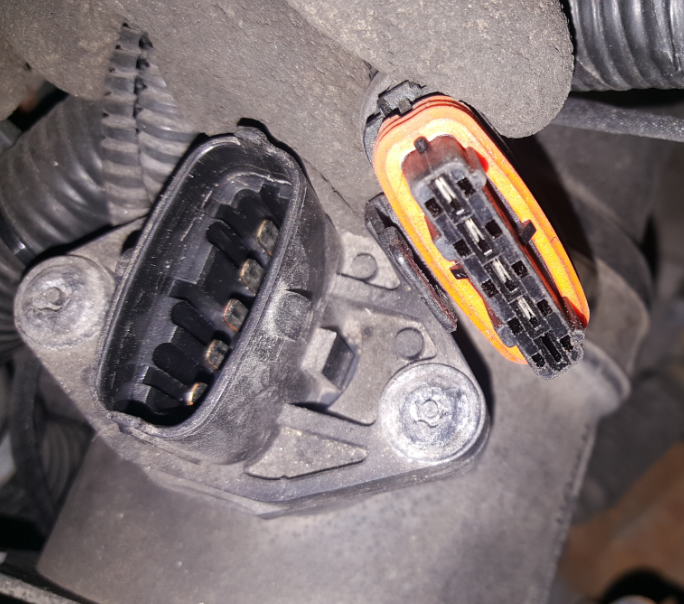
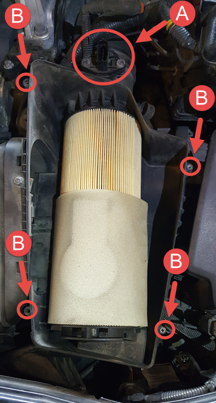
(A) I checked the connector on the MAF sensor which is located just behind the air box. This releases by lifting a small catch on one side.
![Image]()
Terminals all looked pretty clean on male and female sides.
![Image]()
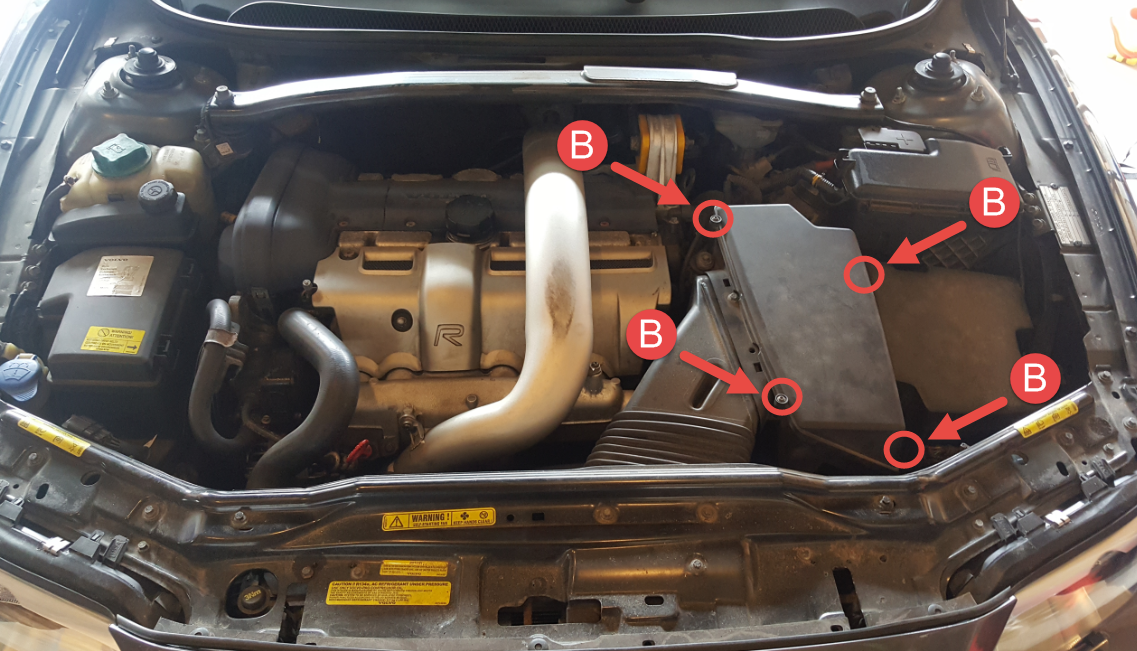
(B) - Took off the air box cover. 4 captive T25 screws. Two are lower down than this shot captured, on the right side.
![Image]()
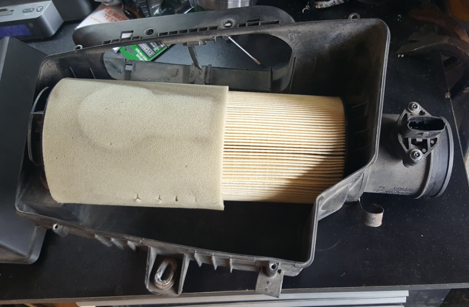
Here's a shot with the cover off. I had just turned the filter over which is why it has that outline on the foam section.
![Image]()
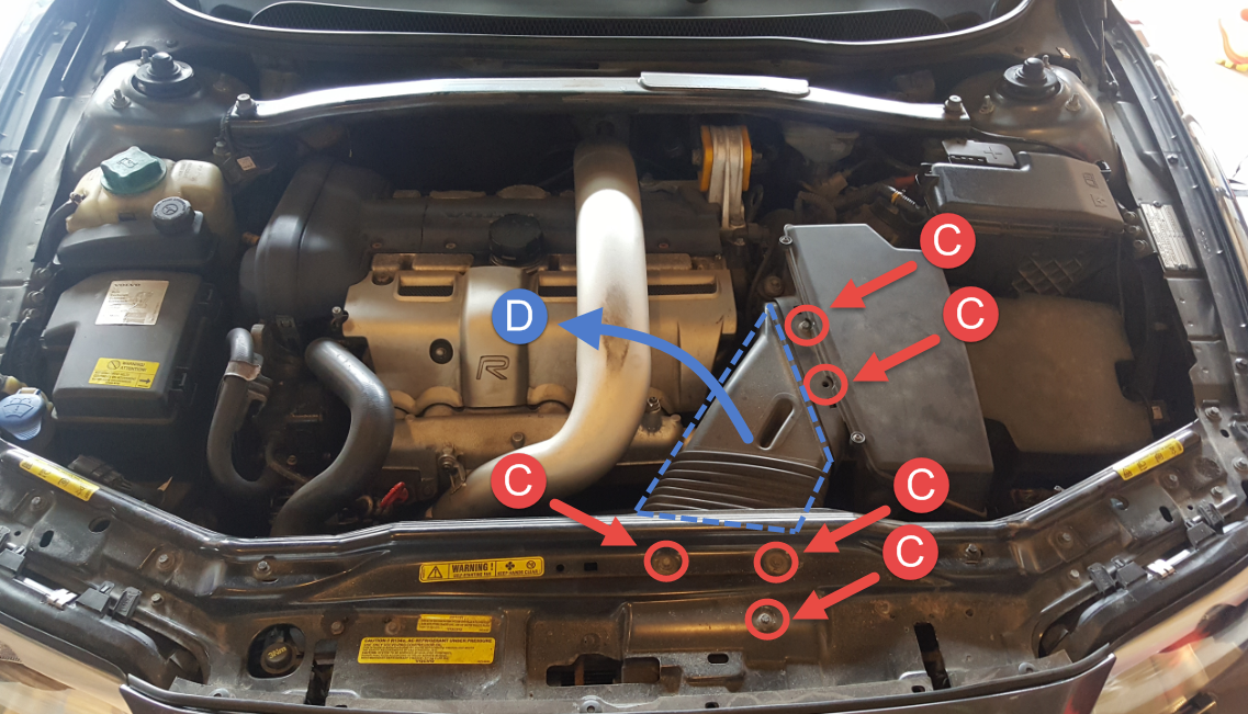
(C) Next, removed the intake duct. 5 bolts, 8mm hex head. Mine is missing one, but I've circled the location anyway. Be careful not to lose the little metal clips that the two bolts on the air box.
(D) Then pull, bend, wiggle, and yank the intake duct out. It's flexible. Yes, the cover to the air box is showing in this shot, I suggest having it off, and the air filter out during this step.
![Image]()
(E) Remove 3, 8mm hex head, that mount the air box.
(F) Loosen off the gear clamp, 7mm hex head, on the MAF assembly. Can't see it in this shot, but the location is indicated. Look a couple points further down when the MAF and air box are removed and you'll see it.
![Image]()
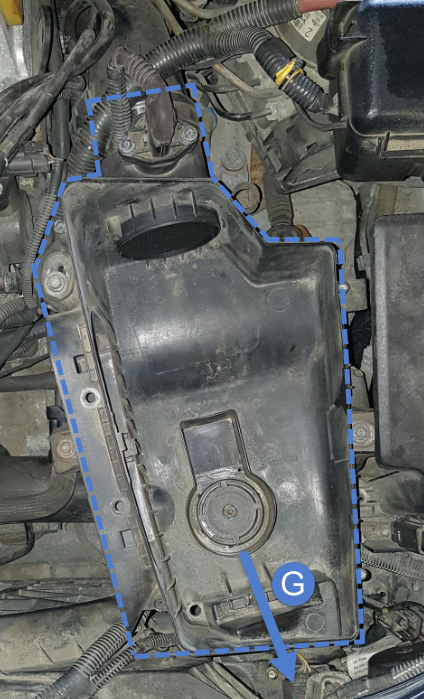
(G) With the mounting hardware removed (E), gear clamp loosened (F), and connector disconnected (A), lift and pull the MAF / air box assembly up and toward the front of the car. It can take a bit of force to get the duct on the MAF to pop free. I did this in 2°C/ 36°F, so anything warmer than that and all of the duct removals should get easier as the material is softer.
![Image]()
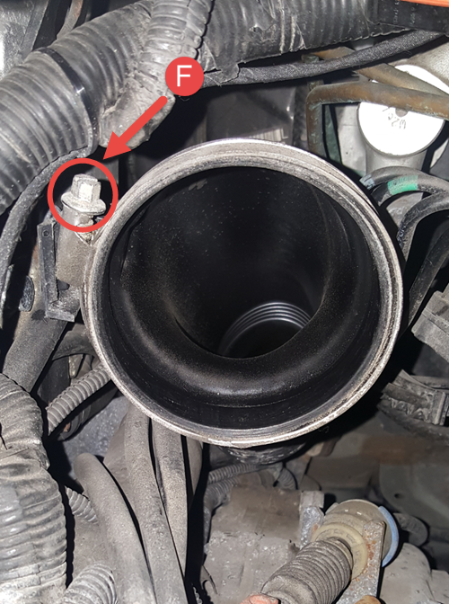
Taking a look down the duct after the MAF is removed, things look fairly clean. (F) is better indicated in this photo.
![Image]()
Shot of the MAF / air box assembly on the bench.
![Image]()
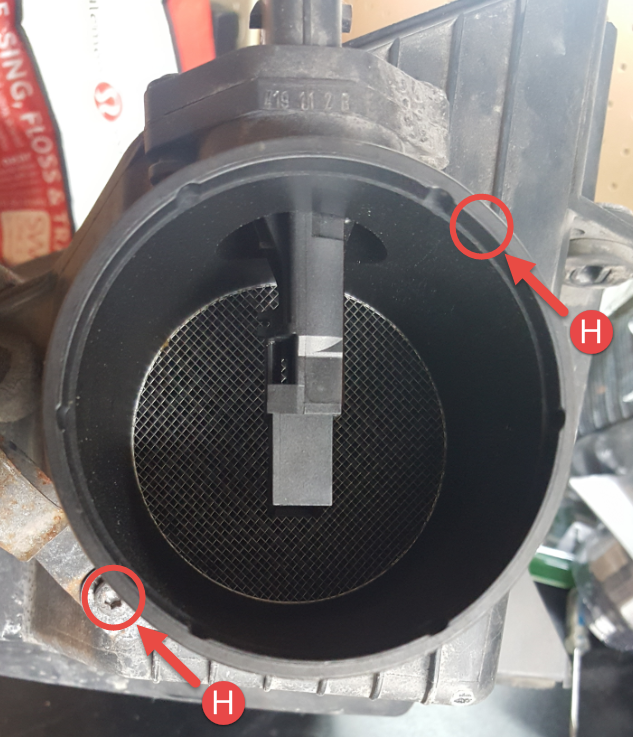
(H) Looking at the MAF output end, there are 2 screws, T25 (I think) holding the MAF assembly onto the air box, remove them and pull the assembly off the air box. One isn't visible in this shot, but location is indicated. One screw also held a clip that wasn't holding anything routed in my car… anyone have ideas what it was intended for??
Please note that these are coarse thread screws going direct into what was once an untapped hole. When putting these back in, to avoid stripping do the following:
1. Turn the screw in reverse (counter-clockwise) with very light pressure applied until you feel the screw 'step'
2. Once the step is felt, start screwing in (clockwise) to follow the existing threads in the plastic. This will avoid running new threads in the plastic and chewing up the hole until it's unusable.
![Image]()
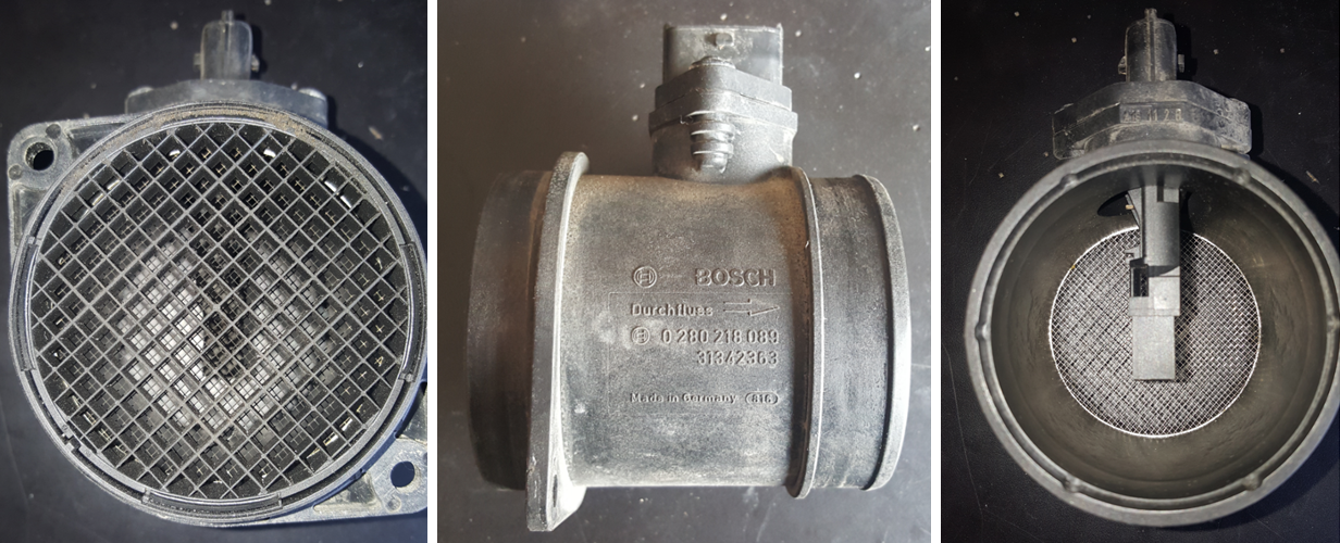
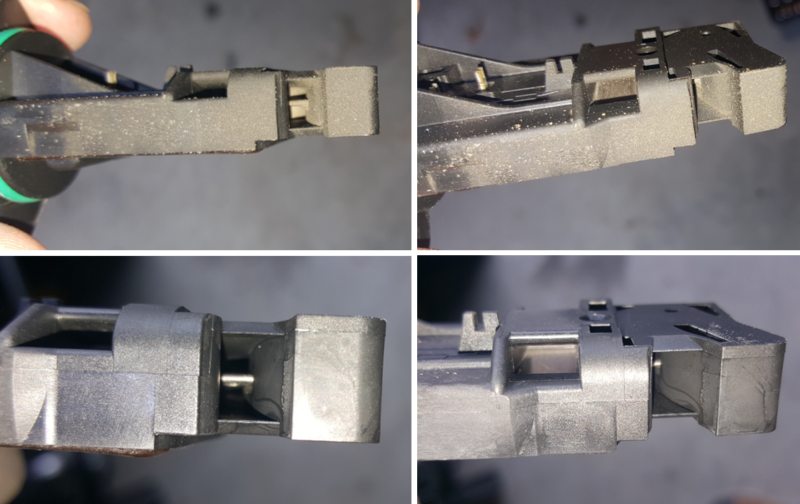
Here are a few shots of the MAF assembly on the bench - this is what you get when you buy a new one as I understand (Volvo PN 31342363). Didn't exactly present the best angles for viewing and especially cleaning the sensor. Need to clean the platinum wires / plates which are presented to the airflow, meaning through the grilles, but I could see that it was somewhat dirty and warranted cleaning to me. So that sucks.
![Image]()
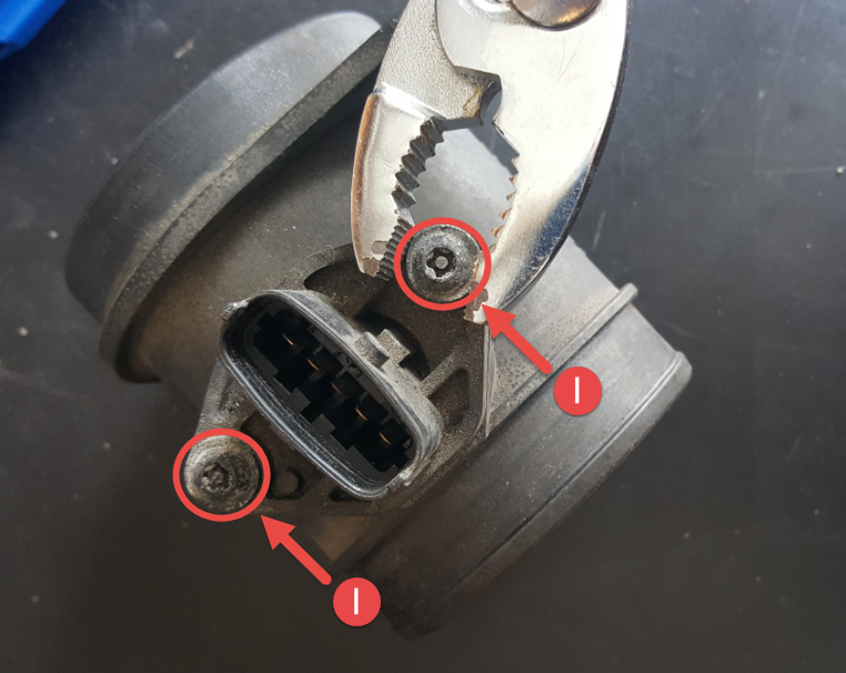
(I) There had to be better access. I don't know about the rest of you, but I don't have 5-point torx security drivers kicking around - or whatever these are. BUT, I have pliers. And these screws have *just* enough of a flange on them to grab and aren't torqued in tightly so I could turn them out. Remove 2 screw, pliers.
![Image]()
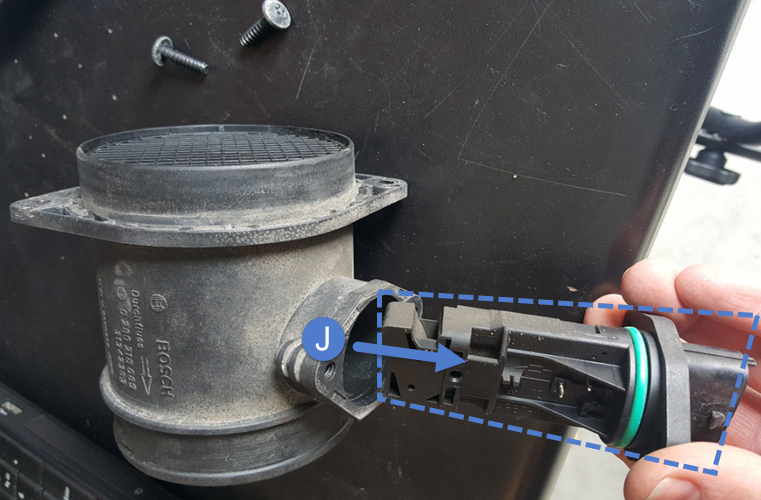
(J) Now that the screws are out, pull. Easy peasy.
![Image]()
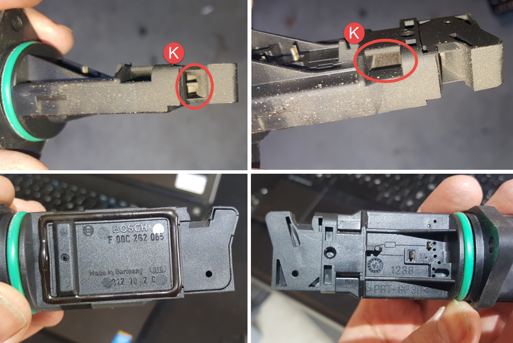
(K) Looking at the filament and the plate (and exposed front face to airflow) there was definitely some dirt/grime build up. I'd like to stress from what I've read so far - DON'T TOUCH THOSE PARTS!! Don't wipe them clean, use a cleaner spray and keep it hands off.
Other than that, everything appeared nice and clean considering it's in the air path. Filters work. I can't say how long this has been in the car. The last owner said this car 'eats' MAF sensors… not sure what that was supposed to mean. On the plus side, this one at least appears to be OEM if it was ever replaced.
![Image]()
Time to clean. I had 'CRC - SensorKleen' which I got from PartSource locally, was cheaper than Canadian Tire, only cost $9+tx (CDN). Below are shots after cleaning to show how/where. I did this outside for ventilation. The can said to spray 10-15 times and let dry, it just cleared everything right off with no trouble, then I let it dry in open air.
![Image]()
Here's a good before / after. After cleaning, pop it back into the housing and use your pliers (or the real tool!) to put the screws back in. Two notes:
1. Make sure you orient the sensor toward the incoming airflow - see photos above for proper orientation. Pretty sure the parts are designed so that they can't go in wrong with holes not lining up, but I didn't try.
2. These screws are into plastic as well, so please observe the note under (H) so that you don't strip out.
![Image]()
If you were only intending to clean your MAF sensor, you're done with that. Now just stick everything back into your engine bay by reversing the steps above. Nothing tricky.
If you still want to go on and clean your throttle body, steady on!
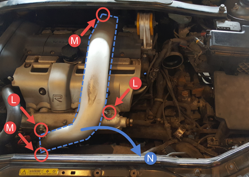
Ok, to get access to the throttle body, we need to pull off two of the charge pipes (maybe these aren't called charge pipes, what do I know, but stick with me). First will be the silver one that runs over the engine - I believe this comes from the turbo and into the intercooler. Second will be the black on deeper down, which comes from the intercooler into the throttle body. Airflow direction shown with green arrows because I can.
![Image]()
(L) Remove 2 screws, T25 torx. The one on the left, I had to use a 1/4 socket on a small ratchet with my T25 quick-bit stuck in it to access because my pic-quick driver wouldn't fit in there.
(M) Loosen off the 2 gear clamps on the duct, should be 7mm hex head. The one in the back, nearest the cabin is a little harder to access, but not bad. While you're back here, unhook that harness from the clip on the back of the charge pipe.
(N) DON'T PULL!! Make sure you unhooked that harness in the back near (M). Ok, now pull damnit, so impatient. Duct out.
![Image]()
(O) - Loosen off these 2 gear clamps, smaller than 7mm, I just used a slot screw driver since they were so accessible. Slip the tubes off the barbs. This will make things possible/easier.
(P) - Loosen off this gear clamp, 7mm hex head. Mine was turned 90deg to that it faced a wall and I had to use vice grips to start it off. Don't ask me how they got it on there in the first place.
![Image]()
(P - the second) If you follow that black charge pipe to the left under the intake manifold? You'll find that it ends at the throttle body with a gear clamp - loosen that off, 7mm hex head. I don't have a superb photo of it, space there was kinda tight and I ended up taking a bunch of videos with my phone under there, just swinging it around to see what I see. Technology is great.
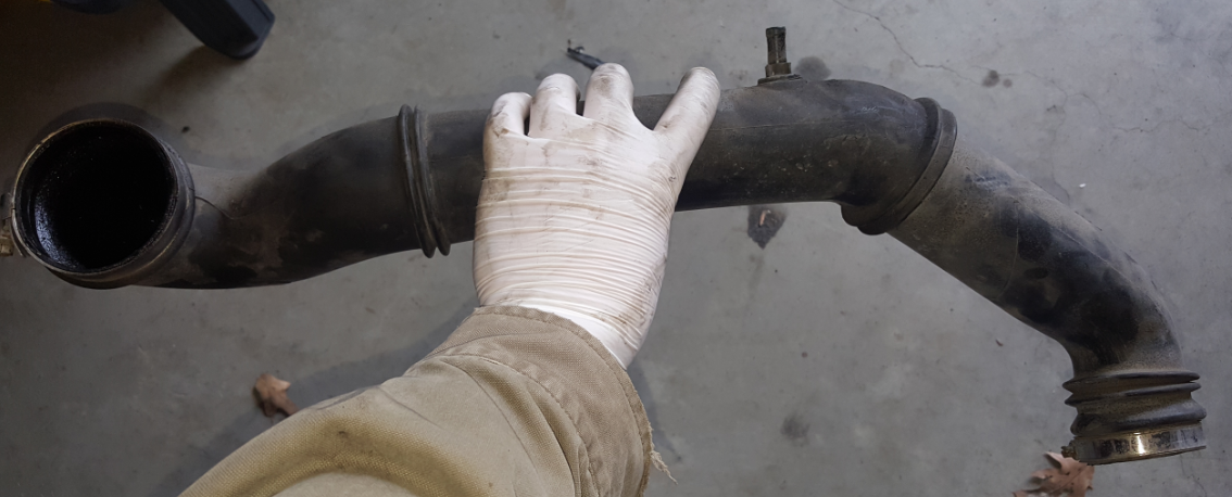
Now that the 2 hoses are off the charge pipe, and the 2 gear clamps are loosened off, you should be able to pull that charge pipe free, and then route it out of that space. It'll look like this.
![Image]()
Now, we're on to actually getting the throttle body out, which is this little guy peeking out from under the intake manifold.
![Image]()
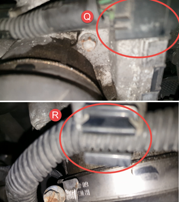
(Q) Before pulling the bolts holding the throttle body, I recommend disconnecting the harness. It's pretty easy, and is accessible from the side we're coming in at, sort of front right - nearest the black cover of the throttle body. Press/lift the retaining clips and then just slide it out.
(R) Also remove the harness from the routing clip on the throttle body casting.
![Image]()
(S) Wish I could say that I have a better shot of the bolts, but again, space. Here's a frame from the re-install video I took where I was checking that everything went together well - so ignore the throttle body looking so clean. There are 4 bolts to remove, 8mm hex head I believe - only 2 shown here. Mine just fell right out when I got the 4th bolt off, and then I just routed it to the right through the space where the black charge pipe used to be.
![Image]()
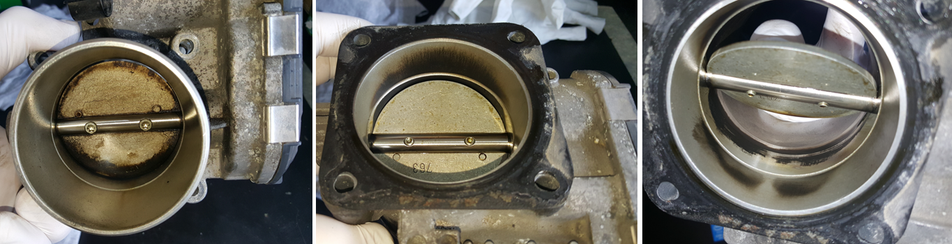
It's out! It's dirty! And it's worse than it looks!
![Image]()
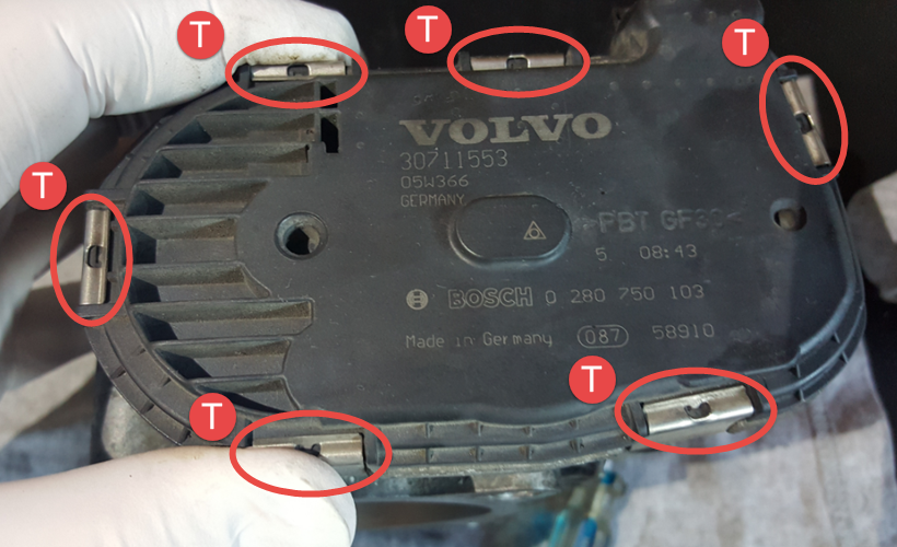
(T) First things first, one of the videos I linked at the top showed that oil managed to get inside the control housing. Time to check that out. Here's the plastic cover, there are 6 clips around the perimeter that can just pry off with a small screw driver. Pry from the casting side so that you don't dig into the plastic housing - the clips are symmetric. Nothing flies free, the cover just peels right off. There is a gasket ring that runs in a channel on the plastic cover inside to keep an eye on, it may pull out and just need to get placed back in.
![Image]()
Oh man, it's an oily mess in here. Luckily the oil seems to have pooled at the bottom and didn't make it up onto the running surfaces of the position strips on the left of the cover. Time for clean-up. I used some small cloths gently on the end of a screw driver. The large light coloured disk can lift right out, no orientation keys or anything.
Any work in here, by careful around the tracing fingers on the yellow-ish gear. They run along the position strip and are likely very sensitive. I just didn't touch them, I didn't need to. Pushing the butterfly valve around inside the throttle body shows the motion this all works through. No problem doing that, there's a return spring.
![Image]()
I'm hailing from Cambridge Ontario, so if you're in the area, gimme a shout! I'll be happy to do a VIDA read if you're in need.
Work I've done so far on the car hasn't been too involved:
1. All new rotors/pads installed
2. Brand new headlights installed
3. Rebuilt headlight wiper motors
I digress, this post is really a 'how-to' on cleaning both the MAF sensor, and throttle body.
If you know your way around all this stuff, I'm actually interested in your input on a few things that made me raise an eyebrow, so you could skip to the end and look at that (or read it all, that's cool too), and I'd really appreciate any insights. Thanks in advance!
Diagnosis:
Couple weeks ago, I had a check engine light come up. I pulled it up and the DTC was 'ECM-121B Mass air flow (MAF) sensor - Flow too low'. I cleared it, and watched to see if it would come up again since I hadn't actually noticed any poor performance while driving.
Just in the last week, the DTC came up again and I would get some pretty reduced engine performance at times - with an audible change in engine note. It would feel like the power suddenly dropped out for a short while even though I still kept accelerating, and then would come back shortly after. Mucking around, I was able to start reproducing it fairly reliably as I would accelerate moderately in 4th (I have an M66), to about 70km/h as I go by 2500rpm.
Here's a shot of the details that I pulled up later.
I also noticed that when I would start the car cold, the engine speed would jump right to idle, around 750rpm. Before all this started happening, it would start just below 2000rpm (sometimes flutter around up there), then shortly drop to 1000rpm, and then a short while later down to idle around 750rpm. So that was new behavior.
VIDA being such a nice tool, with so many sensors accessible and able to feed me information live (even in a plot), I wanted to see what was going on. So, I plugged in with a laptop, picked a few sensors to watch that I thought might be relevant, and went for a drive. I won't bore you with 30min of video capture, and me not realizing the mic was recording, and instead show a screen capture.
I caught 4 good instances of the engine performance drop out (red arrows to indicate), and they all coincided with a sudden drop in the MAF value (blue line), even though I was under constant throttle to accelerate at the time - notice the engine RPM continuing up (green line). I don't know why the vehicle speed wasn't updating in the list, but this was happening around 70km/h.

So I started digging around online for some direction on how to clean a MAF, and also found that the throttle body (TB) downstream can also impact the airflow, and looking into that, it should be cleaned too. Now I had some direction. Below are a couple links to the information I used to figure out what I was going to do, in addition to service instructions within VIDA. It's been stressed in forum posts (and in the VIDA instructions) to replace the TB gasket on removal, so I did that.
Removal/cleaning video:
I also checked local prices for new parts, MAF ~$200+tx, TB ~$415+tx (Canadian prices). So cleaning rather than replacing was my first choice.
Tools / Materials:
• Torx driver set - usually used T25
• Socket set - 7mm, 8mm, 10mm
• Slot screw drivers
• Pliers
• Rags
• MAF cleaner - I used 'CRC, SensorKleen'
• Throttle Body cleaner - I used 'CRC, Throttle Body Kleen'
• New throttle body gasket (Volvo PN: 8636753)
Plan/Steps:
I wrote up my plan and steps to follow based on what I read, so I would botch it and forget something. Feel free to follow these steps!
MAF/TB Removal:
i. Capture Error codes
ii. Watch mass airflow rates and capture (take it for a drive, and record)
iii. Turn off car
iv. Disconnect battery (negative terminal)
v. Check terminals/connectors thoroughly on the MAF
vi. Remove the MAF
vii. Check where the TB bolts are accessible from
viii. Remove charge pipe from over the engine (going into intercooler) for access
ix. Remove charge pipe (coming from intercooler) from intercooler and throttle body
x. Disconnect TB connector and check terminals
xi. Remove 4 bolts from the TB (downward?)
xii. Remove TB - note gasket orientation!!
1) Orientation is raised profile toward engine
Cleaning MAF:
§ Take to work bench, evaluate cleanliness
§ Clean with MAF cleaner (NO TOUCHING) - 10-15 sprays
§ Let dry completely
Cleaning TB:
§ Take to work bench, evaluate cleanliness
§ Clean with TB cleaner on a clean rag/stick combo
§ Open the control housing and inspect for any oils or other corrosions to be cleaned
□ Take care around the terminals
Other Checks:
§ Evaluate the charge pipes for cleanliness, clean where appropriate
Re-install:
§ New gasket on the TB
§ Re-install it all
Removal, cleaning, and reinstalling:
I'll get a bit photo heavy through here, and try to keep everything well labelled as I go through. So strap in.
First, I disconnected the negative battery terminal in my trunk, and tucked the lead away inside a rubber glove to avoid any unexpected contact. Then, on to the engine compartment.
(A) I checked the connector on the MAF sensor which is located just behind the air box. This releases by lifting a small catch on one side.
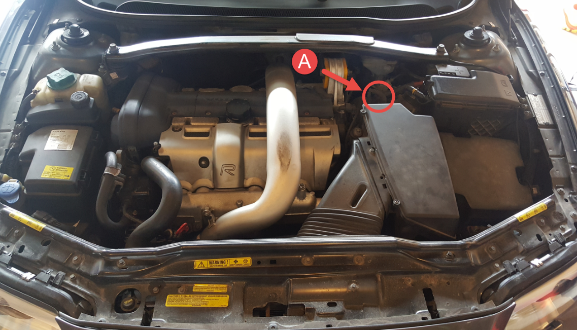
Terminals all looked pretty clean on male and female sides.
(B) - Took off the air box cover. 4 captive T25 screws. Two are lower down than this shot captured, on the right side.
Here's a shot with the cover off. I had just turned the filter over which is why it has that outline on the foam section.
(C) Next, removed the intake duct. 5 bolts, 8mm hex head. Mine is missing one, but I've circled the location anyway. Be careful not to lose the little metal clips that the two bolts on the air box.
(D) Then pull, bend, wiggle, and yank the intake duct out. It's flexible. Yes, the cover to the air box is showing in this shot, I suggest having it off, and the air filter out during this step.
(E) Remove 3, 8mm hex head, that mount the air box.
(F) Loosen off the gear clamp, 7mm hex head, on the MAF assembly. Can't see it in this shot, but the location is indicated. Look a couple points further down when the MAF and air box are removed and you'll see it.

(G) With the mounting hardware removed (E), gear clamp loosened (F), and connector disconnected (A), lift and pull the MAF / air box assembly up and toward the front of the car. It can take a bit of force to get the duct on the MAF to pop free. I did this in 2°C/ 36°F, so anything warmer than that and all of the duct removals should get easier as the material is softer.
Taking a look down the duct after the MAF is removed, things look fairly clean. (F) is better indicated in this photo.
Shot of the MAF / air box assembly on the bench.
(H) Looking at the MAF output end, there are 2 screws, T25 (I think) holding the MAF assembly onto the air box, remove them and pull the assembly off the air box. One isn't visible in this shot, but location is indicated. One screw also held a clip that wasn't holding anything routed in my car… anyone have ideas what it was intended for??
Please note that these are coarse thread screws going direct into what was once an untapped hole. When putting these back in, to avoid stripping do the following:
1. Turn the screw in reverse (counter-clockwise) with very light pressure applied until you feel the screw 'step'
2. Once the step is felt, start screwing in (clockwise) to follow the existing threads in the plastic. This will avoid running new threads in the plastic and chewing up the hole until it's unusable.
Here are a few shots of the MAF assembly on the bench - this is what you get when you buy a new one as I understand (Volvo PN 31342363). Didn't exactly present the best angles for viewing and especially cleaning the sensor. Need to clean the platinum wires / plates which are presented to the airflow, meaning through the grilles, but I could see that it was somewhat dirty and warranted cleaning to me. So that sucks.
(I) There had to be better access. I don't know about the rest of you, but I don't have 5-point torx security drivers kicking around - or whatever these are. BUT, I have pliers. And these screws have *just* enough of a flange on them to grab and aren't torqued in tightly so I could turn them out. Remove 2 screw, pliers.
(J) Now that the screws are out, pull. Easy peasy.
(K) Looking at the filament and the plate (and exposed front face to airflow) there was definitely some dirt/grime build up. I'd like to stress from what I've read so far - DON'T TOUCH THOSE PARTS!! Don't wipe them clean, use a cleaner spray and keep it hands off.
Other than that, everything appeared nice and clean considering it's in the air path. Filters work. I can't say how long this has been in the car. The last owner said this car 'eats' MAF sensors… not sure what that was supposed to mean. On the plus side, this one at least appears to be OEM if it was ever replaced.
Time to clean. I had 'CRC - SensorKleen' which I got from PartSource locally, was cheaper than Canadian Tire, only cost $9+tx (CDN). Below are shots after cleaning to show how/where. I did this outside for ventilation. The can said to spray 10-15 times and let dry, it just cleared everything right off with no trouble, then I let it dry in open air.
Here's a good before / after. After cleaning, pop it back into the housing and use your pliers (or the real tool!) to put the screws back in. Two notes:
1. Make sure you orient the sensor toward the incoming airflow - see photos above for proper orientation. Pretty sure the parts are designed so that they can't go in wrong with holes not lining up, but I didn't try.
2. These screws are into plastic as well, so please observe the note under (H) so that you don't strip out.
If you were only intending to clean your MAF sensor, you're done with that. Now just stick everything back into your engine bay by reversing the steps above. Nothing tricky.
If you still want to go on and clean your throttle body, steady on!
Ok, to get access to the throttle body, we need to pull off two of the charge pipes (maybe these aren't called charge pipes, what do I know, but stick with me). First will be the silver one that runs over the engine - I believe this comes from the turbo and into the intercooler. Second will be the black on deeper down, which comes from the intercooler into the throttle body. Airflow direction shown with green arrows because I can.

(L) Remove 2 screws, T25 torx. The one on the left, I had to use a 1/4 socket on a small ratchet with my T25 quick-bit stuck in it to access because my pic-quick driver wouldn't fit in there.
(M) Loosen off the 2 gear clamps on the duct, should be 7mm hex head. The one in the back, nearest the cabin is a little harder to access, but not bad. While you're back here, unhook that harness from the clip on the back of the charge pipe.
(N) DON'T PULL!! Make sure you unhooked that harness in the back near (M). Ok, now pull damnit, so impatient. Duct out.
(O) - Loosen off these 2 gear clamps, smaller than 7mm, I just used a slot screw driver since they were so accessible. Slip the tubes off the barbs. This will make things possible/easier.
(P) - Loosen off this gear clamp, 7mm hex head. Mine was turned 90deg to that it faced a wall and I had to use vice grips to start it off. Don't ask me how they got it on there in the first place.

(P - the second) If you follow that black charge pipe to the left under the intake manifold? You'll find that it ends at the throttle body with a gear clamp - loosen that off, 7mm hex head. I don't have a superb photo of it, space there was kinda tight and I ended up taking a bunch of videos with my phone under there, just swinging it around to see what I see. Technology is great.
Now that the 2 hoses are off the charge pipe, and the 2 gear clamps are loosened off, you should be able to pull that charge pipe free, and then route it out of that space. It'll look like this.
Now, we're on to actually getting the throttle body out, which is this little guy peeking out from under the intake manifold.

(Q) Before pulling the bolts holding the throttle body, I recommend disconnecting the harness. It's pretty easy, and is accessible from the side we're coming in at, sort of front right - nearest the black cover of the throttle body. Press/lift the retaining clips and then just slide it out.
(R) Also remove the harness from the routing clip on the throttle body casting.
(S) Wish I could say that I have a better shot of the bolts, but again, space. Here's a frame from the re-install video I took where I was checking that everything went together well - so ignore the throttle body looking so clean. There are 4 bolts to remove, 8mm hex head I believe - only 2 shown here. Mine just fell right out when I got the 4th bolt off, and then I just routed it to the right through the space where the black charge pipe used to be.

It's out! It's dirty! And it's worse than it looks!
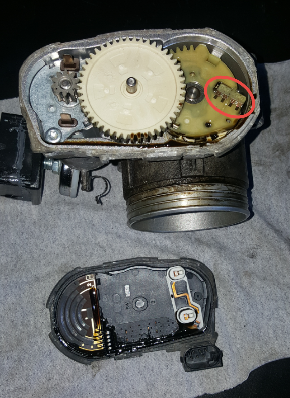
(T) First things first, one of the videos I linked at the top showed that oil managed to get inside the control housing. Time to check that out. Here's the plastic cover, there are 6 clips around the perimeter that can just pry off with a small screw driver. Pry from the casting side so that you don't dig into the plastic housing - the clips are symmetric. Nothing flies free, the cover just peels right off. There is a gasket ring that runs in a channel on the plastic cover inside to keep an eye on, it may pull out and just need to get placed back in.
Oh man, it's an oily mess in here. Luckily the oil seems to have pooled at the bottom and didn't make it up onto the running surfaces of the position strips on the left of the cover. Time for clean-up. I used some small cloths gently on the end of a screw driver. The large light coloured disk can lift right out, no orientation keys or anything.
Any work in here, by careful around the tracing fingers on the yellow-ish gear. They run along the position strip and are likely very sensitive. I just didn't touch them, I didn't need to. Pushing the butterfly valve around inside the throttle body shows the motion this all works through. No problem doing that, there's a return spring.